
Remote.It Connections - How are they made
The ladder diagram in Table 1 below corresponds to a basic Remote.It connection. This example ladder diagram corresponds to establishing an encrypted Remote.It P2P UDP tunnel that carries an ssh connection. This ladder diagram shows the UDP datagram traffic between endpoints during connection.
The ladder diagram was generated directly by Wireshark from a packet trace on the originating client (my home laptop) using a special instrumented version of the Remote.It software. The Remote.It network traffic is encrypted and thus the data, packet types, messages and packet flow cannot be seen by Wireshark or any packet inspection techniques.
Only the start of the connection is shown here, up to the point that data start flowing between the two devices. The originating client local address is 10.0.1.29 (my laptop at home). Two Remote.It servers are involved in the connection process: a Remote.It front-end server and a Remote.It chat server. The Remote.It front-end server address is 174.36.235.146. The Remote.It chat server address is 209.235.201.53.
The target device external IP address is 73.15.2.31 (a RaspberryPi at the office behind a NAT router) on UDP port 55438. This is the IP address of the NAT router and the external IP address of the RaspberryPi. Since the ladder diagram was generated by Wireshark on the originating client (my home laptop) there is no way for Wireshark to know the internal IP address of the RaspberryPi. Only Remote.It knows the RaspberryPi internal IP address which is 10.0.0.123. You also see the RaspberryPi internal IP address 10.0.0.123 on the ladder diagram and we will explain this shortly.
In the ladder diagram below, the arrows have corresponding UDP port numbers in parentheses and thus the arrow heads don’t reach and touch the endpoints, the ladder sides, as is customary in ladder diagrams but this is how Wireshark generates the ASCII version of the ladder diagram (or flow graph as it is called in Wireshark). For example, traffic to and from the originating device (my laptop at 10.0.1.29) is shown on UDP port number 33013, but any port number could be used and in this case, could be specified when the Remote.It software is launched on the originating device. Similarly, the Remote.It front-end server (at 174.36.235.146) traffic is shown on UDP port number 5959, the Remote.It chat server (at 209.235.201.53) traffic is shown on UDP port number 5963, and the RaspberryPi (external address 73.15.2.31) is shown on UDP port number 55438.
You may have noticed we just called what we have been calling the originating device (my laptop), the originating client. That is because I am initiating the Remote.It connection as a Remote.It user and I authenticate with Remote.It using my Remote.It login, which is user at remote.it. If the device itself were originating the connection, we call the originator the originating device (rather than originating client). Remote.It can perform device to device connections and in that case, we would have a true device to device connection without a user login involved. The RaspberryPi at the office is still called the target device.
In the ladder diagram below, the initial four messages exchanged are part of the example authentication process. Remote.It is flexible in how authentication is performed. For example, OAuth or OAuth 2.0 may be used. To illustrate how authentication may be used, we have shown a simple example. Authentication is used to verify the identification of a user as an originating client (or an originating device) to the Remote.It server. Authentication takes a nonce (a one-time use random number) generated by the Remote.It server and sent to the client together with a secret (or password) that is shared by the originating client and the Remote.It server and generates a hash. The hash is sent to the Remote.It server to be authenticated and if the hash sent matches the hash generated by the Remote.It server, then authentication is successful. Successful authentication allows keys to be generated for shared secret keys, encrypting session keys, and for keying server to client encryption. Some, but not all, of the details of key generation and exchange are described below. The authentication traffic is shown tagged as AU in the message explanations below. Once keys have been exchanged all encrypted message traffic is shown tagged as E1 and E2 in the message explanations below. E1 is used to denote encrypted server traffic. E2 is used to denote encrypted P2P traffic between devices. E1 and E2 use separate keys and separate encryption mechanisms.
In the ladder diagram below, the messages such as REQUEST_AUTH_MESSAGE are Remote.It CHAT protocol messages that are contained within UDP datagrams. The Remote.It CHAT protocol is the underlying protocol used by Remote.It to connect devices. Each Remote.It CHAT protocol message has a packet type. In this example trace, the Remote.It CHAT protocol message type has been decoded by a custom Lua Wireshark dissector that I wrote, and that is how you can see the message types in the ladder diagram. It should be emphasized again that Remote.It traffic is encrypted and thus not normally visible without the special version of the Remote.It device software used in this example.
In the ladder diagram below, the elapsed time in seconds from the start of a connection is shown on the left-hand side of the ladder diagram. The start of a connection is, in this simple example, the launch of the Remote.It software on the originating client (my laptop at 10.0.1.29).
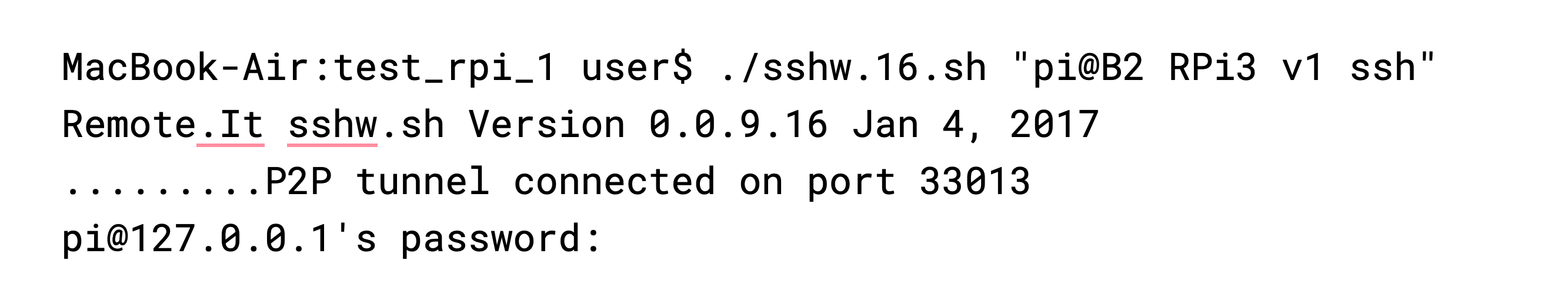
There are two important commands to understand here. The script sshw.16.sh launches the Remote.It software with a known user and a known device, a RaspberryPi, that I own and have rights to connect to and known to Remote.It as the Remote.It service that I have named “B2 RPi3 v1 ssh”. This service is known to Remote.It, because I registered the service with Remote.It, to be of type ssh and to be used for ssh connections. I have asked to be connected to the RaspberryPi as user “pi”. Notice that the script then prints “P2P tunnel connected on port 33013” which means that the P2P tunnel has been established by Remote.It and now the ssh connection using that tunnel can proceed. The next command is the password prompt coming from the remote RaspberryPi via ssh over the Remote.It connection tunnel. Notice very carefully that the prompt is as though the connection were to 127.0.0.1 or a localhost address. We get a localhost address because the Remote.It software terminates the TCP connection and then passes the TCP data on to the host using a separate localhost connection. Using localhost addresses and the localhost interface means a host can be completely hidden or cloaked from the outside as only localhost connections need be allowed. This is a very important feature of the Remote.It system.
In the ladder diagram below, the Remote.It connection process has been shown up to the point that data flows over the established Remote.It connection. In a complete Remote.It connection session several more exchanges of TUNNEL_DATA_MESSAGE and TUNNEL_ACK_MESSAGE would occur as ssh transfers data over the Remote.It connection. Finally, several messages would be exchanged once the connection is terminated, for example I could enter “exit” at the RaspberryPi system prompt.
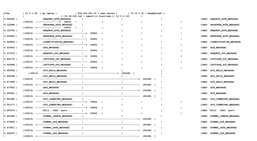
Table 1. A ladder diagram showing how a basic Remote.It connection is established. The originating client local address is 10.0.1.29 (laptop). The Remote.It front-end server address is 174.36.235.146 and Remote.It chat server address is 209.235.201.53. The target device (RaspberryPi) external address is 73.15.2.31 and internal address is 10.0.0.123. This ladder diagram was generated directly by Wireshark from a packet trace on the originating client device using a special version of Remote.It software.
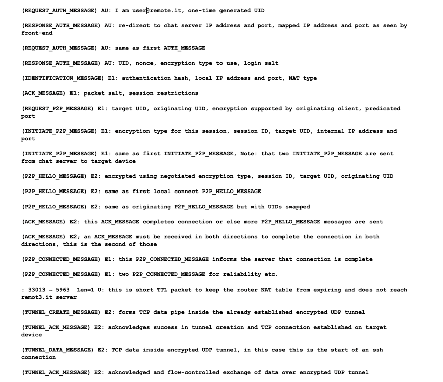
Table 2. Message content and functions for a basic Remote.It connection. Each line in the above table corresponds to a line in the ladder Table 1 diagram. If you view these side-by-side, they should allow you to read across both tables to determine the timing, direction, endpoints, and function of the each Remote.It CHAT protocol message.
Remote.It connection messages
We can now look at the information flow in each Remote.It CHAT protocol message in more detail. Each Remote.It CHAT protocol message below corresponds to each line in the ladder diagram above. Even though I have added more message contents below than are shown above, still not all information is shown: for example, connection and use restrictions, various manufacturing and deployment options may not be shown where they are not essential to understanding how connections are established.
(REQUEST_AUTH_MESSAGE) AU: The first four messages starting with this one, and including this message, are a simple example of secure authentication; and these four datagrams are flagged as “AU”. This is a message from my laptop to the Remote.It front-end server that “I am m*****@remote.it”, and containing a one-time generated originating client UID that will be used to identify this connection session, and the last-connected IP address and port.
(RESPONSE_AUTH_MESSAGE) AU: A re-direct to the Remote.It chat server IP address and port, also contains the NAT mapped IP address and port as seen by the Remote.It front-end server.
(REQUEST_AUTH_MESSAGE) AU: Same as first REQUEST_AUTH_MESSAGE message but re-directed to the Remote.It chat server IP address and port.
(RESPONSE_AUTH_MESSAGE) AU: A message from the Remote.It front-end server to my laptop. Contains: originating client UID, a nonce (one-time random number), the encryption type to use, login salt (seed added to data before encryption), and also the NAT mapped IP address and port as seen as by the Remote.It chat server. The NAT mapped IP address and port as seen by the Remote.It front-end server together with the NAT mapped IP address and port as seen as by the Remote.It chat server are used by Remote.It to help determine the NAT type.
(IDENTIFICATION_MESSAGE) E1: Note that from now on all Remote.It server traffic is encrypted (all datagrams that are encrypted using this encryption type are flagged as E1). Contains: SPI, packet salt, (auth hash), (sequence number). ()= not used, local IP address and port, NAT type, client flags (manufacturing ID etc.), protocol support (TCP tunnel), P2P encryption supported, and use restrictions.
(ACK_MESSAGE) E1: Contains: SPI, packet salt, session restrictions.
(REQUEST_P2P_MESSAGE) E1: Contains: SPI, salt, target device UID (data type 0x0a), originating client or my UID (data type 0x01), encryption supported by the originating client, predicated port if required by NAT type, and use restrictions. This is an important message as it contains the UID of the target device that I want to connect to.
(INITIATE_P2P_MESSAGE) E1: Contains: SPI, salt. Note that two identical INITIATE_P2P_MESSAGE messages are sent as a result of tuning experience for reliability and speed. Contains: SPI, salt, encryption type to use for this session, session ID, target device UID, internal IP address and port ort if required by NAT type, and use restrictions.
(INITIATE_P2P_MESSAGE) E1: This message is the same as first INITIATE_P2P_MESSAGE. Note: that two INITIATE_P2P_MESSAGE are sent from the Remote.It chat server to the target device for reliability and speed.
(P2P_HELLO_MESSAGE) E2: This message is encrypted using the negotiated encryption type. Contains: session ID, target device UID, originating client UID, maximum packet size, maximum outstanding requests which is related to the buffer depth. Note this message is a connection attempt to the RaspberryPi local address 10.0.0.123, which is known only to Remote.It. For example, it could be that my laptop at 10.0.1.29 can be routed to 10.0.0.123. In this case, it cannot. This mechanism is important as it may allow connection in some unusual NAT and network environments.
(P2P_HELLO_MESSAGE) E2: This message is exactly same as first local connect P2P_HELLO_MESSAGE to the target device, but now to the target device RaspberryPi external IP address 73.15.2.31. Note: that whichever P2P_HELLO_MESSAGE reaches destination first (either originating client or target device) will complete the P2P connection.
(P2P_HELLO_MESSAGE) E2: exactly same as the P2P_HELLO_MESSAGE from the originating client but with swapped UIDs.
(ACK_MESSAGE) E2: This ACK_MESSAGE completes P2P connection or else more P2P_HELLO_MESSAGE messages are sent.
(ACK_MESSAGE) E2; The ACK_MESSAGE must flow in both directions to complete the P2P connection in both directions.
(P2P_CONNECTED_MESSAGE) E1: This ACK_MESSAGE informs the Remote.It server that connection is complete.
(P2P_CONNECTED_MESSAGE) E1: Note that two P2P_CONNECTED_MESSAGE messages are sent for reliability etc.
: 33013 → 5963 Len=1 U: This is a packet with deliberately short TTL to keep the required router NAT table parameters from expiring. This packet does not actually reach the Remote.It server.
(TUNNEL_CREATE_MESSAGE) E2: This message is triggered by any TCP connection establishment process. For example, ssh when started will establish a TCP connection. This message will cause the formation of a TCP data pipe inside the already established encrypted UDP tunnel. Note that Remote.It software on each device terminates the TCP connection. TCP data and only the TCP data is then passed to the host via a localhost connection, for example with a 127.0.0.1 address. There is therefore no TCP header inside the Remote.It UDP tunnel. This means there is never any TCP header information conveyed using Remote.It. This means that even if somehow multiple layers of encryption are broken and the TCP data is exposed, there is nothing that can be done with that TCP data; there is no routable information.
(TUNNEL_ACK_MESSAGE) E2: This message acknowledges success in the encrypted Remote.It P2P UDP tunnel creation and that TCP connection is established on target device else we try TUNNEL_CREATE_MESSAGE again.
(TUNNEL_DATA_MESSAGE) E2: This message contains TCP data (and only TCP data, with no TCP header information) inside the encrypted Remote.It P2P UDP tunnel.
(TUNNEL_ACK_MESSAGE) E2: This message acknowledges and performs a flow-controlled exchange of data over the encrypted Remote.It P2P UDP tunnel.
More Remote.It details
In the Wireshark trace that we used for the connection ladder diagram above, we did not show the UDP packet contents. If we had shown those UDP datagrams we would see the TCP data and TCP connections details (flow control and so forth), but we would not see any TCP header information. This means that even if multiple layers of encryption in a Remote.It connection were to be somehow broken, the TCP data that would be uncovered is not usable since there is no header and thus no routing information.
In the Wireshark trace that we used for the connection ladder diagram we did not show the UDP packet lengths and total data use. The Remote.It CHAT protocol is designed to have very low overhead and includes messages that allow data usage monitoring for example.
In the Wireshark trace that we used for the connection ladder diagram it is not apparent that Remote.It connections appear to be a 127.0.0.1 connection. This is as a result of the Remote.It device software terminating the TCP connection carried inside the encrypted Remote.It P2P UDP tunnel. This is a very important feature as it allows the host device to close all ports in a cloaked fashion. Only 127.0.0.1 or other localhost connections need be allowed.